Saturday 1 December 2012

Defining Throughput


Defining Throughput

Remember the previous post "Bandwidth and throughput". it turns out to be difficult to define precisely the throughput of a switch. Intuitively, we might think that if a switch has n inputs that each support a link speed of si , then the throughput would just be the sum of all the si . This is actually the best possible throughput that such a switch could provide, but in practice almost no real switch can guarantee that level of performance. One reason for this is simple to understand. Suppose that, for some period of time, all the traffic arriving at the switch needed to be sent to the same output. As long as the bandwidth of that output is less than the sum of the input bandwidths, then some of the traffic will need to be either buffered or dropped. With this particular traffic pattern, the switch could not provide a sustained throughput higher than the link speed of that one output. However, a switch might be able to handle traffic arriving at the full link speed on all inputs if it is distributed across all the outputs evenly; this would be considered optimal.

Another factor that affectsthe performance of switches is the the size of packets arriving on the inputs. For an ATM switch, this is normally not an issue because all “packets” (cells) are the same length. But for  Ethernet switches or IP routers, packets of widely varying sizes are possible. Some of the operations that a switch must perform have a constant overhead per packet, so a switch is likely to perform differently depending on whether all arriving packets are very short, very long, or mixed. For this reason, routers or switches that forward variable-length packets are often characterized by a packet per second (pps) rate as well as a throughput in bits per second. The pps rate is usually measured with minimum-sized packets.

The first thing to notice about this discussion is that the throughput of the switch is a function of the traffic to which it is subjected. One of the things that switch designersspend a lot of their time doing is trying to come up with traffic models that approximate the behavior of real data traffic. It turns out that it is extremely difficult to achieveaccurate models.

A traffic model attempts to answer several important questions: (1) When do packets arrive? (2) What outputs are they destined for? And (3) how big are they? Traffic modeling is a wellestablished science that has been extremely successful in the world of telephony, enabling telephone companies to engineer their networks to carry expected loads quite efficiently. This is partly because the way people use the phone network does not change that much over time: The frequency with which calls are placed, the amount of time taken for a call, and the tendency of everyone to make calls on Mother’s Day have stayed fairly constant for many years.4 By contrast, the rapid evolution of computer communications, where a new application like Napster can change the traffic patterns almost overnight, has made effective modeling of computer networks much more difficult. To give you a sense of the range of throughputs that designers need to be concerned about, a high-end router used in the Internet at the time of writing might support 10 OC-192 links for a throughput of approximately 100 Gbps. A 100- Gbps switch, if called upon to handle a steady stream of 64-byte packets, would need a packet per second
rate of

100 × 109 ÷ (64 × 8)
= 195 × 106 pps

Friday 5 October 2012

Optical Switching


Optical Switching

To a casual observer of the networking industry around the year 2000, it might have appeared that the most interesting sort of switching was optical switching. Indeed, optical switching did become an important technology in the late 1990s, due to a confluence of several factors. One factor was the commercial availability of dense wavelength division multiplexing (DWDM) equipment, which makes it possible to send a great deal of information down a single fiber by transmitting on a large number of optical wavelengths (or colors) at once. Thus, for example, you might send data on 100 or more different wavelengths, and each wavelength might carry as much as 10 Gbps of data.
Optical Switching
Optical Switching

A second factor was the commercial availability of optical amplifiers. Optical signals are attenuated as they pass through fiber, and after some distance (about 40 km or so) they need to be made stronger in some way. Before optical amplifiers, it was necessary to place repeaters in the path to recover the optical signal, convert it to a digital electronic signal, and then convert it back to optical again. Before you could  get the data into a repeater, you would have to demultiplex it using a DWDM terminal. Thus, a large number of DWDMterminals would be needed just to drive a single fiber pair for a long distance. Optical amplifiers, unlike repeaters, are analog devices that boost whatever signal is sent along the fiber, even if it is sent on a hundred different wavelengths. Optical amplifiers therefore made DWDM gear much more attractive, because now a pair of DWDM terminals could talk to each other when separated by a distance of hundreds of kilometers. Furthermore, you could even upgrade the DWDM gear at the ends without touching the optical amplifiers in the middle of the path, because they will amplify 100 wavelengths as easily as 50 wavelengths.

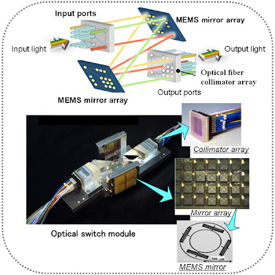
With DWDM and optical amplifiers, it became possible to build optical networks of huge capacity. But at least one more type of device is needed to make these networks useful—the opti- cal switch. Most so-called optical switches today actually perform their switching function electronically, and from an architectural point of view they have more in common with the circuit switches of the telephone network than the packet switches described in next post. A typical optical switch has a large number of interfaces that understand SONET framing and is able to cross-connect a SONET channel from an incoming interface to an outgoing interface. Thus, with an optical switch, it becomes possible to provide SONET channels from point A to point B via point C even if there is no direct fiber path from A to B—there just needs to be a path from A to C, a switch at C, and a path from C to B. In this respect, an optical switch bears some relationship to the switches, in that it creates the illusion of a connetion between two points even when there is no direct physical connection between them. However, optical switches do not provide virtual circuits; they provide “real” circuits (e.g., a SONET channel). There are even some newer types of optical switches that use microscopic mirrors to deflect all the light from one switch port to another, so that there could be an uninterrupted optical channel from point A to point B. We don’t cover optical networking extensively in this book, in part because of space considerations. For many practical purposes, you can think of optical networks as a piece of the infrastructure that enables telephone companies to provide SONET links or other types of circuits where and when you need them. However, it is worth noting that many of the technologies that are discussed later in this book, such as routing protocols and Multiprotocol Label Switching, do have application to the world of optical networking.

Wednesday 8 August 2012

Frames, Buffers, and Messages


Frames, Buffers,and Messages


As this section has suggested, the network adaptor is the place where the network comes in physical contact with the host. It also happens to be the place where three different worlds intersect: the network, the host architecture, and the host operating system. It turns out that each of these has a different terminology for talking about the same thing. It is important to recognize when this is happening.

From the network’s perspective, the adaptor transmits frames from the host and receives frames into the host. Most of this chapter has been presented from the network perspective, so you should have a good understanding of what the term “frame” means. From the perspective of the host architecture, each frame is received into or transmitted from a buffer, which is simply a region of main memory of some length and starting at some address. Finally, from the operating system’s perspective, a message is an abstract object that holds network frames. Messages are implemented by a data structure that includes pointers to different memory locations (buffers).

happy reading^^...

Friday 15 June 2012

Error Detection or Error Correction?

Error Detection or Error Correction

We have mentioned that it is possible to use codes that not only detect the presence of errors but also enable errors to be corrected. Since the details of such codes require yet more complex mathematics than that required to understand CRCs, we will not dwell on them here. However, it is worth considering the merits of correction versus detection.

At first glance, it would seem that correction is always better, since with detection we are forced to throw away the message and, in general, ask for another copy to be transmitted. This uses up bandwidth
and may introduce latency while waiting for the retransmission. However, there is a downside to correction: It generally requires a greater number of redundant bits to send an error-correcting code that is as strong (that is, able to cope with the same range of errors) as a code that only detects errors. Thus, while error detection requires more bits to be sent when errors occur, error correction requires more bits to be sent all the time. As a result, error correction tends to be most useful when (1) errors are quite probable, as they may be, for example, in a wireless environment, or (2) the cost of retransmission is too high, for example, because of the latency involved in retransmitting a packet over a satellite link.

The use of error-correcting codes in networking is sometimes referred to as forward error cor- rection (FEC) because the correction of errors is handled “in advance” by sending extra information, rather than waiting for errors to happen and dealing with them later by retransmission.

Thursday 17 May 2012

Bit Rates and Baud Rates


Bit Rates and Baud Rates

Many people use the terms bit rate and baud rate interchangeably, even though as we see with the Manchester encoding, they are not the same thing. While the Manchester encoding is an example of a case in which a link’s baud rate is greater than its bit rate, it is also possible to have a bit rate that is greater than the baud rate. This would imply that more than one bit is encoded on each pulse sent over the link.

To see how this might happen, suppose you could transmit four distinguished signals over a link rather than just two. On an analog link, for example, these four signals might correspond to four different frequencies. Given four different signals, it is possible to encode two bits of information on each signal. That is, the first signal means 00, the second signal means 01, and so on. Now, a sender (receiver) that is able to transmit (detect) 1000 pulses per second would be able to send (receive) 2000 bits of information per second. That is, it would be a 1000-baud/2000-bps link.

Friday 6 April 2012

How Big Is a Mega?


Mega in Computer Network

Mega

There are several pitfalls you need to be aware of when working with the common units of networking— MB, Mbps, KB, and Kbps. The first is to distinguish carefully between bits and bytes. Throughout this book, we always use a lowercase b for bits and a capital B for bytes. The second is to be sure you are using the appropriate definition of mega (M) and kilo (K). Mega, for example, can mean either 220 or 106. Similarly, kilo can be either 210 or 103. What is worse, in networking we  typically use both definitions. Here’s why.

Network bandwidth, which is often specified in terms of Mbps, is typically governed by the speed of the clock that paces the transmission of the bits. A clock that is running at 10 MHz is used to transmit bits at 10 Mbps. Because the mega in MHz means 106 hertz, Mbps is usually also defined as 106 bits per second. (Similarly, Kbps is 103 bits per second.) On the other hand, when we talk about a message that we want to transmit, we often give its size in kilobytes. Because messages are stored in the computer’s memory, and memory is typically measured in powers of two, the K in KB is usually taken to mean 210. (Similarly, MB usually means 220.) When you put the two together, it is not uncommon to talk about sending a 32-KB message over a 10-Mbps channel, which should be interpreted to mean 32 × 210 × 8 bits are being transmitted at a rate of 10×106 bits per second. This is the interpretation we use throughout the book, unless explicitly stated otherwise. The good news is that many times we are satisfied with a back-of-the-envelope calculation, in which case it is perfectly reasonable to pretend that a byte has 10 bits in it (making it easy to convert between bits and bytes) and that 106 is really equal to 220 (making it easy to convert between the two definitions of mega). Notice that the first approximation introduces a 20% error, while the latter introduces only a 5% error. To help you in your quickand- dirty calculations, 100 ms is a reasonable number to use for a cross-country round-trip time—at least when the country in questionis the United States—and 1 ms is a good approximation of an RTT across a local area network. In the case of the former, we increase the 48-ms round-trip time implied by the speed of light over a fiber to 100 ms because there are, as we have said, other sources of delay, such as the processing time in the switches inside the network. You can also be sure that the path taken by the fiber between two points will not be a straight line.

Thursday 15 March 2012

SANs, LANs, MANs, and WANs


SANs, LANs, MANs, and WANs

Characterize Network

One way to characterize networks is according to their size. Two wellknown examples are LANs (local area networks) and WANs (wide area networks); the former typically extend less than 1 km, while the latter can be worldwide. Other networks are classified as MANs (metropolitan area networks), which usually span tens of kilometers. The reason such classifications are interesting is that the size of a network often has implications for the underlying technology that can be used, with a key factor being the amount of time it takes for data to propagate from one end of the network to the other; we discuss this issue more in later articles.


An interesting historical note is that the term “wide area network” was not applied to the first WANs because there was no other sort of network to differentiate them from. When computers were incredibly rare and expensive, there was no point in thinking about how to connect all the computers in the local area—there was only one computer in that area. Only as computers began to proliferate did LANs become necessary, and the term “WAN” was then introduced to describe the larger networks that interconnected geographically distant computers.

Another kind of network that we need to be aware of is SANs (system area networks). SANs are usually confined to a single room and connect the various components of a large computing system. For example, HiPPI (High Performance Parallel Interface) and Fiber Channel are two common SAN technologies used to connect massively parallel processors to scalable storage servers and data vaults. (Because they often connect computers to storage servers, SANs are sometimes defined as storage area networks.) Although this article does not describe such networks in detail, they are worth knowing about because they are often at the leading edge in terms of performance, and because it is increasingly common to connect such networks into LANs and WANs.

Friday 9 March 2012

Bandwidth and Throughput


Bandwidth and 
Throughput


Bandwidth and throughput are two of the most confusing terms used in networking. While we could try to give you a precise definition of each term, it is important that you know how other people might use them and for you to be aware that they are often used interchangeably. First of all, bandwidth is literally a  measure of the width of a frequency band. For example, a voice-grade telephone line supports a frequency band ranging from 300 to 3300 Hz; it is said to have a bandwidth of 3300 Hz 300 Hz = 3000 Hz. If you see the word “bandwidth” used in a situation in which it is being measured in hertz, then it probably refers to the range of signals that can be accommodated.

When we talk about the bandwidth of a communication link, we normally refer to the number of bits per second that can be transmitted on the link. We might say that the bandwidth of an Ethernet is 10 Mbps. A useful distinction might be made, however, between the bandwidth that is available on the link and the number of bits per second that we can actually transmit over the link in practice. We tend to use the word “throughput” to refer to the measured perfor- mance of a system. Thus, because of various inefficiencies of implementation, a pair of nodes connected by a link with a bandwidth of 10 Mbps might achieve a throughput of only 2 Mbps. This would mean that an application on one host could send data to the other host at 2 Mbps.

Finally, we often talk about the bandwidth requirements of an application—the number of bits per second that it needs to transmit over the network to perform acceptably. For some applications, this might be “whatever I can get”; for others, it might be some fixed number (preferably no more than the  available link bandwidth); and for others, it might be a number that varies with time. I will provide more on this topic later in this blog.

Keep reading^^….

Wednesday 29 February 2012

Connectivity in Computer Network (Cont'd)


Connectivity

Connection

Connectivity (Cont'd). A second way in which a set of computers can be indirectly connected is shown in Figure interconnection network. In this situation, a set of independent networks (clouds) are interconnected to form an internetwork, or internet for short. We adopt the Internet’s convention of referring to a generic internetwork of networks as a lowercase i internet, and the currently operational TCP/IP Internet as the capital I Internet. A node that is connected to two or more networks is commonly called a router or gateway, and it plays much the same role as a switch—it forwards messages from one network to another. Note that an internet can itself be viewed as another kind of network, which means that an internet can be built from an interconnection of internets. Thus, we can recursively build arbitrarily large networks by interconnecting clouds to form larger clouds.

Interconnection Network
Interconnection Networks

Just because a set of hosts are directly or indirectly connected to each other does not mean that we have succeeded in providing host-to-host connectivity. The final requirement is that each node must be able to say which of the other nodes on the network it wants to communicate with. This is done by assigning an address to each node. An address is a byte string that identifies a node; that is, the network can use a node’s address to distinguish it from the other nodes connected to the network. When a source node wants the network to deliver a message to a certain destination node, it specifies the address of the destination node. If the sending and receiving nodes are not directly connected, then the switches and routers of the network use this address to decide how to forward the message toward the destination. The process of determining systematically how to forward messages toward the destination node based on its address is called routing.

This brief introduction to addressing and routing has presumed that the source node wants to send a message to a single destination node (unicast). While this is the most common scenario, it is also possible that the source node might want to broadcast a message to all the nodes on the network. Or a source node might want to send a message to some subset of the other nodes, but not all of them, a situation called multicast. Thus, in addition to node-specific addresses, another requirement of a network is that it support multicast and broadcast addresses.

The main idea to take away from this discussion is that we can define a network recursively as consisting of two or more nodes connected by a physical link, or as two or more networks connected by a node. In other words, a network can be constructed from a nesting of networks, where at the bottom level, the network is implemented by some physical medium. One of the key challenges in providing network connectivity is to define an address for each node that is reachable on the network (including support for broadcast and multicast connectivity), and to be able to use this address to route messages toward the appropriate destination node(s).

Friday 17 February 2012

Connectivity in Computer Network


Connectivity

Starting with the obvious, a network must provide connectivity among a set of computers. Sometimes it is enough to build a limited network that connects only a few select machines. In fact, for reasons of privacy and security, many private (corporate) networks have the explicit goal of limiting the set of machines that are connected. In contrast, other networks (of which the Internet is the prime example) are designed to grow in a way that allows them the potential to connect all the computers in the world. A system that is designed to support growth to an arbitrarily large size is said to scale. Using the Internet as a model, this book addresses the challenge of scalability. 

Links, Nodes, and Clouds

 Network connectivity occurs at many different levels. At the lowest level, a network can consist of two or more computers directly connected by some physical medium, such as a coaxial cable or an optical fiber. We call such a physical medium a link, and we often refer to the computers it connects as nodes. (Sometimes a node is a more specialized piece of hardware rather than a computer, but we overlook that distinction for the purposes of this discussion.) As illustrated in Figure , physical links are sometimes limited to a pair of nodes (such a link is said to be point-to-point), while in other cases, more than two nodes may share a single physical link (such a link is said to be multiple access). Whether a given link supports point-to-point or multipleaccess connectivity depends on how the node is attached to the link. It is also the case that multiple-access links are often limited in size, in terms of both the geographical distance they can cover and the number of nodes they can connect. The exception is a satellite link, which can cover a wide geographic area.

point to point
Point to Point

Multiple Access
Multiple Access

If computer networks were limited to situations in which all nodes are directly connected to each other over a common physical medium, then either networks would be very limited in the number of computers they could connect, or the number of wires coming out of the back of each node would quickly become both unmanageable and very expensive. Fortunately, connectivity between two nodes does not necessarily imply a direct physical connection between them—indirect connectivity may be achieved among a set of cooperating nodes. Consider the following two examples of how a collection of computers can be indirectly connected.

Switched Network
Switched Network


Figure Switched Network shows a set of nodes, each of which is attached to one or more pointto- point links. Those nodes that are attached to at least two links run software that forwards data received on one link out on another. If organized in a systematic way, these forwarding nodes form a switched network. There are numerous types of switched networks, of which the two most common are circuit switched and packet switched. The former is most notably employed by the telephone system, while the latter is used for
the overwhelming majority of computer networks and will be the focus of this blog.

The important feature of packet-switched networks is that the nodes in such a network send discrete blocks of data to each other. Think of these blocks of data as corresponding to some piece of application data such as a file, a piece of email, or an image. We call each block of data either a packet or a message, and for now we use these terms interchangeably; we discuss the reason they are not always the same in next article. Packet-switched networks typically use a strategy called store-and-forward. As the name suggests, each node in a store-and-forward network first receives a complete packet over some link, stores the packet in its internal memory, and then forwards the complete packet to the next node. In contrast, a circuit-switched network first establishes a dedicated circuit across a sequence of links and then allows the source node to send a stream of bits across this circuit to a destination node. The major reason for using packet switching rather than circuit switching in a computer network is efficiency, discussed in the next subsection.

The cloud in Figure 1.3 distinguishes between the nodes on the inside that implement the network (they are commonly called switches, and their sole function is to store and forward packets) and the nodes on the outside of the cloud that use the network (they are commonly called hosts, and they support users and run application programs). Also note that the cloud in Figure 1.3 is one of the most important icons of computer networking. In general, we use a cloud to denote any type of network, whether it is a single point-to-point link, a multiple-access link, or a switched network. Thus, whenever you see a cloud used in  a figure, you can think of it as a placeholder for any of the networking technologies covered in this blog.

Wednesday 1 February 2012

Requirements for Computer Network


Requirements 

We have just established an ambitious goal for ourselves: to understand how to build a computer network from the ground up. Our approach to accomplishing this goal will be to start from first principles, and then ask the kinds of questions we would naturally ask if building an actual network. At each step, we will use today’s protocols to illustrate various design choices available to us, but we will not accept these existing artifacts as gospel. Instead, we will be asking (and answering) the question of why networks are designed the way they are. While it is tempting to settle for just understanding the way it’s done today, it is important to recognize the underlying concepts because networks are constantly changing as the technology evolves and new applications are invented. It is our experience that once you understand the fundamental ideas, any new protocol that you are confronted with will be relatively easy to digest.

The first step is to identify the set of constraints and requirements that influence
network design. Before getting started, however, it is important to understand that the
expectations you have of a network depend on your perspective:
An application programmer would list the services that his or her application
needs, for example, a guarantee that each message the application sends will
be delivered without error within a certain amount of time.
A network designer would list the properties of a cost-effective design, for
example, that network resources are efficiently utilized and fairly allocated to
different users.
A network provider would list the characteristics of a system that is easy to
administer and manage, for example, in which faults can be easily isolated
and where it is easy to account for usage.

This post attempts to distill these different perspectives into a high-level introduction to the major considerations that drive network design, and in doing so, identifies the challenges addressed throughout the rest of this blog… happy reading^^..

Sunday 15 January 2012

Introducing Web Applications


Web Applications

Web Applications
Web Applications

After knowing the fundamental of Computer Network, we move to web applications. Most people know the Internet through its applications: the World Wide Web, email, streaming audio and video, chat rooms, and music (file) sharing. The Web, for example, presents an intuitively simple interface. Users view pages full of textual and graphical objects, click on objects that they want to learn more about, and a corresponding new page appears. Most people are also aware that just under the covers, each selectable object on a page is bound to an identifier for the next page to be viewed. This identifier, called a uniform resource locator (URL), uniquely names every possible page that can be viewed from your Web browser. For example,

http://www.sharetelecommunication.blogspot.com/computer-network

is the URL for a page representing this book at Morgan Kaufmann: The string http indicates that the HyperText Transfer Protocol (HTTP) should be used to download the page, www.facebook.com is the name of the machine that serves the page, and computer-network uniquely identifies the page at the publisher’s site.

What most Web users are not aware of, however, is that by clicking on just one such URL, as many as 17 messages may be exchanged over the Internet, and this assumes the page itself is small enough to fit in a single message. This number includes up to six messages to translate the server name (www.sharetelecommunication.blogspot.com)  into its Internet address (xxx.xxx.xxx.xxx), three messages to set up a Transmission Control Protocol (TCP) connection between your browser and this server, four messages for your browser to send the HTTP “get” request and the server to respond with the requested page (and for each side to acknowledge receipt of that message), and four messages to tear down the TCP connection. Of course, this does not include the millions of messages exchanged by Internet nodes throughout the day, just to let each other know that they exist and are ready to serve Web pages, translate names to addresses, and forward messages toward their ultimate destination.

Although not yet as common as surfing the Web, another emerging application of the Internet is streaming audio and video. Although an entire video file could first be fetched from a remote machine and then played on the local machine, similar to the process of downloading and displaying a Web page, this would entail waiting for the last second of the video file to be delivered before starting to look at it. Streaming video implies that the sender and the receiver are, respectively, the source and the sink for the video stream. That is, the source generates a video stream (perhaps using a video capture card), sends it across the Internet in messages, and the sink displays the stream as it arrives. UC Berkeley. The others include a whiteboard application (wb) that allows users to send sketches and slides to each other, a visual audio tool called vat, and a session directory (sdr) that is used to create and advertise videoconferences. All these tools run on Unix—hence their lowercase names—and are freely available on the Internet. Similar tools are available for other operating systems.

Although they are just two examples, downloading pages from the Web and participating in a videoconference demonstrate the diversity of applications that can be built on top of the Internet and hint at the complexity of the Internet’s design. Starting from the beginning, and addressing one problem at a time, the rest of this book explains how to build a network that supports such a wide range of applications. Chapter 9 concludes the book by revisiting these two specific applications, as well as several others that have become popular on today’s Internet.

To be more precise, video is not an application; it is a type of data. One example of a video application is video-on-demand, which reads a preexisting movie from disk and transmits it over the network. Another kind of application is videoconferencing, which is actually the more interesting case because it has very tight timing constraints. Just as when using the telephone, the interactions among the participants must be timely. When a person at one end gestures, then that action must be displayed at the other end as quickly as possible. Too much delay makes the system unusable. In contrast, if it takes several seconds from the time the user starts the video until the first image is displayed, then the service is still deemed satisfactory. Also, interactive video usually implies that video is flowing in both directions, while a video-on-demand application is most likely sending video in only one direction.

Sunday 1 January 2012

Firstly, The Computer Network


Computer Network

Computer Network
Computer Network

Suppose you want to build a computer network, one that has the potential to grow to global proportions and to support applications as diverse as teleconferencing,video-on-demand, electronic commerce, distributed computing, and digital libraries. What available technologies would serve as the underlying building blocks, and what kind of software architecture would you design to integrate these building blocks into an effective communication service? Answering this question is the overriding goal of this book—to describe the available building materials and then to show how they can be used to construct a network from the ground up.

Before we can understand how to design a computer network, we should first agree on exactly what a computer network is. At one time, the term network meant the set of serial lines used to attach dumb terminals to mainframe computers. To some, the term implies the voice telephone network. To others, the only interesting network is the cable network used to disseminate video signals. The main thing these networks have in common is that they are specialized to handle one particular kind of data (keystrokes, voice, or video) and they typically connect to special-purpose devices (terminals, hand receivers, and television sets).

What distinguishes a computer network from these other types of networks? Probably the most important characteristic of a computer network is its generality. Computer networks are built primarily from general-purpose programmable hardware,and they are not optimized for a particular application like making phone calls or delivering television signals. Instead, they are able to carry many different types of data, and they support a wide, and ever-growing, range of applications. This chapter looks at some typical applications of computer networks and discusses the requirements that a network designer who
wishes to support such applications must be aware of.

Once we understand the requirements, how do we proceed? Fortunately, we will not be building the first network. Others, most notably the community of researchers responsible for the Internet, have gone before us. We will use the wealth of experience generated from the Internet to guide our design. This experience is embodied in a net- work architecture that identifies the available hardware and software components and shows how they can be arranged to form a complete network system.

Therefore, I will try to Share and give those kind of things. And we raise together and be better…good luck^^..