Friday, 11 January 2013

Bridges, Switches, and Routers


Bridges, Switches, and Routers

It is easy to become confused about the distinction between bridges, switches, and routers. There is good reason for such confusion, since at some level, they all forward messages from one link to another. One distinction people make is based on layering: Bridges are linklevel nodes (they forward frames from one link to another to implement an extended LAN), switches are network-level nodes (they forward packets from one link to another to implement a packetswitched network), and routers are internet-level nodes (they forward datagrams from one network to another to implement an internet). In some sense, however, this is an artificial distinction. It is certainly the case that networking companies do not ask the layering police for permission to sell new products that do not fit neatly into one layer or another.
bridges-switches-routers


For example, we have already seen that a multiport bridge is usually called an Ethernet switch or LAN switch. Thus the distinction between bridges and switches has now been largely eroded. For this reason, bridges and switches are often grouped together as “layer 2 devices,” where layer 2 in this context means “above the physical layer, below the internet layer.”

There is, however, an important distinction between LAN switches (or bridges) and ATM switches (and other switches thatare used in WANs, such as Frame Relay and X.25 switches). LAN switches and bridges depend on the spanning tree algorithm, while WAN switches generally run routing protocols that allow each switch to learn the topology of the whole network. This is an important distinction because knowing the whole network topology allows the switches to discriminate among different routes, while in contrast, the spanning tree algorithm locks in a single tree over which messages are forwarded. It is also the case that the spanning tree approach does not scale as well.

What about switches and routers? Are they fundamentallythe same thing, or are they different in some important way? Here, the distinction is much less clear. For starters, since a single point-topoint link is itself a legitimate network, a router can be used to connect a set of such links. In such a situation, a router looks just like a switch. It just happens to be a switch that forwards IP packets using a datagram forwarding model and IP routing protocols.

One big difference between an ATM network built from switches and the Internet built from routers is that the Internet is able to accommodate heterogeneity, whereas ATM consists of homogeneous links. This support for heterogeneity is one of the key reasons why the Internet is so widely deployed.

Saturday, 1 December 2012

Defining Throughput


Defining Throughput

Remember the previous post "Bandwidth and throughput". it turns out to be difficult to define precisely the throughput of a switch. Intuitively, we might think that if a switch has n inputs that each support a link speed of si , then the throughput would just be the sum of all the si . This is actually the best possible throughput that such a switch could provide, but in practice almost no real switch can guarantee that level of performance. One reason for this is simple to understand. Suppose that, for some period of time, all the traffic arriving at the switch needed to be sent to the same output. As long as the bandwidth of that output is less than the sum of the input bandwidths, then some of the traffic will need to be either buffered or dropped. With this particular traffic pattern, the switch could not provide a sustained throughput higher than the link speed of that one output. However, a switch might be able to handle traffic arriving at the full link speed on all inputs if it is distributed across all the outputs evenly; this would be considered optimal.

Another factor that affectsthe performance of switches is the the size of packets arriving on the inputs. For an ATM switch, this is normally not an issue because all “packets” (cells) are the same length. But for  Ethernet switches or IP routers, packets of widely varying sizes are possible. Some of the operations that a switch must perform have a constant overhead per packet, so a switch is likely to perform differently depending on whether all arriving packets are very short, very long, or mixed. For this reason, routers or switches that forward variable-length packets are often characterized by a packet per second (pps) rate as well as a throughput in bits per second. The pps rate is usually measured with minimum-sized packets.

The first thing to notice about this discussion is that the throughput of the switch is a function of the traffic to which it is subjected. One of the things that switch designersspend a lot of their time doing is trying to come up with traffic models that approximate the behavior of real data traffic. It turns out that it is extremely difficult to achieveaccurate models.

A traffic model attempts to answer several important questions: (1) When do packets arrive? (2) What outputs are they destined for? And (3) how big are they? Traffic modeling is a wellestablished science that has been extremely successful in the world of telephony, enabling telephone companies to engineer their networks to carry expected loads quite efficiently. This is partly because the way people use the phone network does not change that much over time: The frequency with which calls are placed, the amount of time taken for a call, and the tendency of everyone to make calls on Mother’s Day have stayed fairly constant for many years.4 By contrast, the rapid evolution of computer communications, where a new application like Napster can change the traffic patterns almost overnight, has made effective modeling of computer networks much more difficult. To give you a sense of the range of throughputs that designers need to be concerned about, a high-end router used in the Internet at the time of writing might support 10 OC-192 links for a throughput of approximately 100 Gbps. A 100- Gbps switch, if called upon to handle a steady stream of 64-byte packets, would need a packet per second
rate of

100 × 109 ÷ (64 × 8)
= 195 × 106 pps

Friday, 5 October 2012

Optical Switching


Optical Switching

To a casual observer of the networking industry around the year 2000, it might have appeared that the most interesting sort of switching was optical switching. Indeed, optical switching did become an important technology in the late 1990s, due to a confluence of several factors. One factor was the commercial availability of dense wavelength division multiplexing (DWDM) equipment, which makes it possible to send a great deal of information down a single fiber by transmitting on a large number of optical wavelengths (or colors) at once. Thus, for example, you might send data on 100 or more different wavelengths, and each wavelength might carry as much as 10 Gbps of data.
Optical Switching
Optical Switching

A second factor was the commercial availability of optical amplifiers. Optical signals are attenuated as they pass through fiber, and after some distance (about 40 km or so) they need to be made stronger in some way. Before optical amplifiers, it was necessary to place repeaters in the path to recover the optical signal, convert it to a digital electronic signal, and then convert it back to optical again. Before you could  get the data into a repeater, you would have to demultiplex it using a DWDM terminal. Thus, a large number of DWDMterminals would be needed just to drive a single fiber pair for a long distance. Optical amplifiers, unlike repeaters, are analog devices that boost whatever signal is sent along the fiber, even if it is sent on a hundred different wavelengths. Optical amplifiers therefore made DWDM gear much more attractive, because now a pair of DWDM terminals could talk to each other when separated by a distance of hundreds of kilometers. Furthermore, you could even upgrade the DWDM gear at the ends without touching the optical amplifiers in the middle of the path, because they will amplify 100 wavelengths as easily as 50 wavelengths.

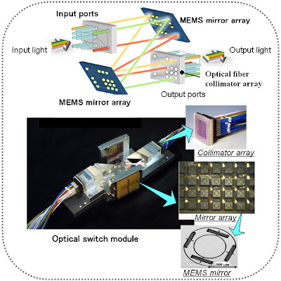
With DWDM and optical amplifiers, it became possible to build optical networks of huge capacity. But at least one more type of device is needed to make these networks useful—the opti- cal switch. Most so-called optical switches today actually perform their switching function electronically, and from an architectural point of view they have more in common with the circuit switches of the telephone network than the packet switches described in next post. A typical optical switch has a large number of interfaces that understand SONET framing and is able to cross-connect a SONET channel from an incoming interface to an outgoing interface. Thus, with an optical switch, it becomes possible to provide SONET channels from point A to point B via point C even if there is no direct fiber path from A to B—there just needs to be a path from A to C, a switch at C, and a path from C to B. In this respect, an optical switch bears some relationship to the switches, in that it creates the illusion of a connetion between two points even when there is no direct physical connection between them. However, optical switches do not provide virtual circuits; they provide “real” circuits (e.g., a SONET channel). There are even some newer types of optical switches that use microscopic mirrors to deflect all the light from one switch port to another, so that there could be an uninterrupted optical channel from point A to point B. We don’t cover optical networking extensively in this book, in part because of space considerations. For many practical purposes, you can think of optical networks as a piece of the infrastructure that enables telephone companies to provide SONET links or other types of circuits where and when you need them. However, it is worth noting that many of the technologies that are discussed later in this book, such as routing protocols and Multiprotocol Label Switching, do have application to the world of optical networking.

Wednesday, 8 August 2012

Frames, Buffers, and Messages


Frames, Buffers,and Messages


As this section has suggested, the network adaptor is the place where the network comes in physical contact with the host. It also happens to be the place where three different worlds intersect: the network, the host architecture, and the host operating system. It turns out that each of these has a different terminology for talking about the same thing. It is important to recognize when this is happening.

From the network’s perspective, the adaptor transmits frames from the host and receives frames into the host. Most of this chapter has been presented from the network perspective, so you should have a good understanding of what the term “frame” means. From the perspective of the host architecture, each frame is received into or transmitted from a buffer, which is simply a region of main memory of some length and starting at some address. Finally, from the operating system’s perspective, a message is an abstract object that holds network frames. Messages are implemented by a data structure that includes pointers to different memory locations (buffers).

happy reading^^...

Friday, 15 June 2012

Error Detection or Error Correction?

Error Detection or Error Correction

We have mentioned that it is possible to use codes that not only detect the presence of errors but also enable errors to be corrected. Since the details of such codes require yet more complex mathematics than that required to understand CRCs, we will not dwell on them here. However, it is worth considering the merits of correction versus detection.

At first glance, it would seem that correction is always better, since with detection we are forced to throw away the message and, in general, ask for another copy to be transmitted. This uses up bandwidth
and may introduce latency while waiting for the retransmission. However, there is a downside to correction: It generally requires a greater number of redundant bits to send an error-correcting code that is as strong (that is, able to cope with the same range of errors) as a code that only detects errors. Thus, while error detection requires more bits to be sent when errors occur, error correction requires more bits to be sent all the time. As a result, error correction tends to be most useful when (1) errors are quite probable, as they may be, for example, in a wireless environment, or (2) the cost of retransmission is too high, for example, because of the latency involved in retransmitting a packet over a satellite link.

The use of error-correcting codes in networking is sometimes referred to as forward error cor- rection (FEC) because the correction of errors is handled “in advance” by sending extra information, rather than waiting for errors to happen and dealing with them later by retransmission.

Thursday, 17 May 2012

Bit Rates and Baud Rates


Bit Rates and Baud Rates

Many people use the terms bit rate and baud rate interchangeably, even though as we see with the Manchester encoding, they are not the same thing. While the Manchester encoding is an example of a case in which a link’s baud rate is greater than its bit rate, it is also possible to have a bit rate that is greater than the baud rate. This would imply that more than one bit is encoded on each pulse sent over the link.

To see how this might happen, suppose you could transmit four distinguished signals over a link rather than just two. On an analog link, for example, these four signals might correspond to four different frequencies. Given four different signals, it is possible to encode two bits of information on each signal. That is, the first signal means 00, the second signal means 01, and so on. Now, a sender (receiver) that is able to transmit (detect) 1000 pulses per second would be able to send (receive) 2000 bits of information per second. That is, it would be a 1000-baud/2000-bps link.

Friday, 6 April 2012

How Big Is a Mega?


Mega in Computer Network

Mega

There are several pitfalls you need to be aware of when working with the common units of networking— MB, Mbps, KB, and Kbps. The first is to distinguish carefully between bits and bytes. Throughout this book, we always use a lowercase b for bits and a capital B for bytes. The second is to be sure you are using the appropriate definition of mega (M) and kilo (K). Mega, for example, can mean either 220 or 106. Similarly, kilo can be either 210 or 103. What is worse, in networking we  typically use both definitions. Here’s why.

Network bandwidth, which is often specified in terms of Mbps, is typically governed by the speed of the clock that paces the transmission of the bits. A clock that is running at 10 MHz is used to transmit bits at 10 Mbps. Because the mega in MHz means 106 hertz, Mbps is usually also defined as 106 bits per second. (Similarly, Kbps is 103 bits per second.) On the other hand, when we talk about a message that we want to transmit, we often give its size in kilobytes. Because messages are stored in the computer’s memory, and memory is typically measured in powers of two, the K in KB is usually taken to mean 210. (Similarly, MB usually means 220.) When you put the two together, it is not uncommon to talk about sending a 32-KB message over a 10-Mbps channel, which should be interpreted to mean 32 × 210 × 8 bits are being transmitted at a rate of 10×106 bits per second. This is the interpretation we use throughout the book, unless explicitly stated otherwise. The good news is that many times we are satisfied with a back-of-the-envelope calculation, in which case it is perfectly reasonable to pretend that a byte has 10 bits in it (making it easy to convert between bits and bytes) and that 106 is really equal to 220 (making it easy to convert between the two definitions of mega). Notice that the first approximation introduces a 20% error, while the latter introduces only a 5% error. To help you in your quickand- dirty calculations, 100 ms is a reasonable number to use for a cross-country round-trip time—at least when the country in questionis the United States—and 1 ms is a good approximation of an RTT across a local area network. In the case of the former, we increase the 48-ms round-trip time implied by the speed of light over a fiber to 100 ms because there are, as we have said, other sources of delay, such as the processing time in the switches inside the network. You can also be sure that the path taken by the fiber between two points will not be a straight line.